Showing posts with label Bab 1. Membuat Gambar Rencana. Show all posts

Sunday, February 20, 2011

> Menggambar Proyeksi Bangunan

Uraian pada bagian ini merupakan uraian umum mengenai gambar
proyeksi bangunan. Gambar proyeksi yang diuraikan adalah gambar
proyeksi perspektif. Untuk dasar-dasar dari menggambar proyeksi dapat
dilihat dan dipelajari dalam buku-buku dasar menggambar teknik
bangunan.

Menggambar proyeksi perspektif adalah salah satu cara
pengungkapan ide/gagasan atau imajinasi yang sangat natural (dalam arti
sesuai dengan kemampuan pandangan mata) dan mudah dimengerti oleh
pemberi tugas atau orang lain yang bukan ahli bangunan/arsitek. Hal
tersebut disebabkan, gambar proyeksi perspektif memperlihatkan rencana
ruang-ruang (space) dan massa bangunan dalam bentuk tiga dimensi.

Untuk dapat membuat gambar proyeksi perspektif diperlukan pedoman
gambar kerja/bestek berupa; gambar denah, potongan melintang,
potongan memanjang, tampak depan, samping kiri, dan kanan dengan
skala yang benar.

Dengan kemampuan dan kemahiran menerapkan skala pada
gambar denah, potongan, dan tampak secara proyeksi perspektif, akan diperoleh
gambar proyeksi perspektif yang mendekati realita/kenyataan pandangan
terhadap rencana bangunan sebenarnya.

Pembuatan gambar proyeksi perspektif terdiri dari dua sudut pandang, yaitu;
1. Gambar proyeksi perspektif menggunakan dua titik lenyap setinggi mata orang
(ibarat orang memotret dengan berdiri tegak). Gambar proyeksi perspektif
model ini sering digunakan para arsitek untuk menggambar proyeksi
perspektif, karena obyek bangunannya tidak terlalu besar dan
menampakkan bentuk bangunan 3 (tiga) dimensi dengan jelas,

2. Pengambilan gambar perspektif menggunakan dua titik lenyap
dengan mata burung (bird eye). Gambar proyeksi perspektif dengan
model ini dilakukan bila obyek bangunannya besar sekali, dan bentuk
bangunan akan tampak semuanya, tetapi prosentasenya lebih banyak
terlihat bagian atap bangunan (ibarat orang memotret dengan memanjat
pohon yang tinggi atau naik di atas menara). Model proyeksi perspektif ini
jarang digunakan para arsitek karena tidak dapat menampakkan gambar
bangunan dengan jelas.

> Membuat Gambar Kerja dan Daftar Komponen

Gambar kerja merupakan dasar bagi pelaksana untuk melakukan
pekerjaan bangunan di lapangan. Gambar kerja didasarkan dari gambar
konstruksi yang memuat detail-detail dari setiap komponen pekerjaan
bangunan.

Beberapa komponen yang gambar kerja adalah;
1. Gambar pondasi,
2. Gambar penulangan beton (sloof, kolom, dan ring balok),
3. Gambar dinding dan plesteran,
4. Gambar kusen (pintu dan jendela) beserta daunnya,
5. Gambar kuda-kuda dan atap,
6. Gambar plafon,
7. Gambar Instalasi air dan plumbing, dan
8. Gambar instalasi listrik.

Untuk memahmi lebih lanjut tentang gambar kerja, maka
disarankan untuk mempelajarinya pada buku-buku menggambar
konstruksi bangunan gedung.

> Menggambar Sketsa

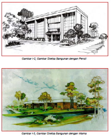
Gambar sketsa adalah pembuatan gambar tanpa melalui alat bantu
menggambar yang biasa digunakan, yaitu penggaris. Alat bantu yang digunakan
dalam gambar sketsa adalah imajinasi dan penalaran pandangan mata. Gambar
sketsa sering digunakan oleh para arsitek dalam merencanakan bangunan. Yang
sering digunakan adalah sketsa untuk merencanakan interior dan eksterior
bangunan.

Gambar sketsa juga sering digunakan untuk menggambar proyeksi perspektif.
Gambar tersebut dihasilkan tanpa melalui bantuan gambar denah,
potongan, dan tampak. Dasar yang digunakan dalam menggambar sketsa
proyeksip perspektif, baik interior maupun eksterior adalah imajinasi dan penalaran
pandangan mata yang cekatan dan kuat dalam alam pikiran seseorang.

Gagasan tentang rancangan bentuk rumah/bangunan sudah tergambar secara
menyeluruh dalam imajinasi dan penalaran. Bila hasil sketsa tersebut akan
diterapkan dalam pembuatan bangunan, maka dari gambar sketsa yang
dihasilkan tersebut baru dibuat gambar rencana secara lengkap yang meliputi
denah, potongan, dan tampak.

> Membaca Gambar Konstruksi

Gambar konstruksi untuk merencanakan dan membuat suatu
bangunan terdiri atas; gambar denah, gambar potongan, dan gambar tampak.

1. Gambar Denah

Denah merupakan salah satu bagian terpenting dari suatu gambar
konstruksi. Denah berasal dari kata latin "planum" yang berarti “dasar”.
Lebih jauh diartikan sebagai lantai atau tempat dimana kita berpijak. Gambar
denah sebenarnya adalah gambar potongan suatu bangunan dalam bidang
datar dengan ketinggian antara ±80-100 cm di atas lantai normal (lantai yang
mempunyai ketinggian dari titik duga ±0.00).

Tujuan pembuatan gambar denah adalah untuk menjelaskan ruangruang
tiga dimensional yang direncanakan, baik dari segi hubungan maupun
fungsinya. Oleh sebab itu, pada gambar denah memuat batas-batas ruang,
arah dari membukanya pintu/jendela, notasi-notasi ketinggian lantai . Gambar
denah tersebut informatif bila saat dilihat/dibaca dapat dirasakan dimensi
dan keleluasaan ruang serta dapat mengenal fungsin ruang.


2. Gambar Potongan
Gambar potongan adalah gambar bangunan yang
diproyeksikan pada bidang vertikal dan posisinya diambil pada tempat-tempat
tertentu, terutama adalah duga lantai yang negatip (turun). Gambar potongan
menunjukkan semua bahan-bahan, baik eksterior maupun interior yang
akan digunakan dan dilengkapi dengan petunjuk-petunjuk yang merupakan
kunci dari sistem bangunan tersebut, seperti bagian-bagian mekanikal,
plumbing dan sebagainya. Fungsi gambar potongan adalah menunjukkan
proporsi ruang interior dan penyelesaiannya.

Gambar potongan terdiri atas potongan melintang dan memanjang.


3. Gambar Tampak
Gambar proyeksi orthogonal, sehingga secara grafis terlihat
sebagai gambar dua dimensi yang datar. Gambar tampak terdiri atas 4
(empat) sisi pandang, yaitu tampak muka, samping kiri, samping kanan,
dan belakang.

Gambar tampak harus memperlihatkan;
a. Karakter dari bangunan itu sendiri.
b. Proporsi dan skala terhadap manusia (pemakainya).
c. Segi-segi lain yang menyangkut perihal ekspresi keindahan serta
hubungannya dengan gambar denah dan gambar potongan yang
memperlihatkan konstruksinya.


4. Gambar Rencana
Gambar denah, potongan, dan tampak biasanya disatukan dalam
satu kertas gambar sebagai satu kesatuan dari gambar rencana
bangunan. Hal tersebut merupakan merupakan dasar dari pelaksanaan
pekerjaan bangunan. Selain itu, keberadaan gambar-gambar tersebut
diperlukan dalam mengurus Ijin Mendirikan Bangunan (IMB).

Sunday, February 13, 2011

> Reading the Image Construction

Construction drawings to plan and create a
building consists of: the floor plan, picture pieces, and pictures appear.


1. Image Map
Plan is one of the most important parts of an image
construction. Plan comes from the Latin word "planum" which means "foundation".
Further defined as a floor or a place where we stand. Image
floor plan is actually a piece of drawing a building in the field
flat with an altitude between ± 80-100 cm above the normal floor (floor
has the height of the expected point of ± 0.00).

The purpose of making the floor plan is to describe the spaces
planned three-dimensional, both in terms of relationships and
function. Therefore, on the floor plan includes the boundaries of space,
direction of the open door / window, floor height notations. Image
informative if the current plan is viewed / perceived dimensions can be read
and flexibility of space and can recognize fungsin space.


2. Figure Pieces
Figure piece is an image building
projected on the vertical plane and the position taken in the places
particular, is primarily a negative predictive floor (down). Figure pieces
showing all materials, both exterior and interior
will be used and comes with instructions that are
of key building systems, such as mechanical parts,
plumbing and so forth. The function of image pieces is to show
the proportion of interior space and its completion.
Figure piece consists of pieces crosswise and lengthwise.


3. Picture Looks
Figure orthogonal projection, so graphically seen
as a flat two-dimensional image. Image appears consists of 4
(Four) side view, namely the facade, left side, right side,
and rear.
Image appears should show;
a. The character of the building itself.
b. Proportion and scale of the human (the user).
c. Other aspects concerning the subject of beauty and expression
relationship with the floor plan and image pieces
shows its construction.


4. Picture Plan
The floor plan, cut, and seemed generally united in
one drawing paper as a unity of plan drawing
building. This is the basis of implementation
building work. In addition, the existence of these pictures
required in the care of Building Permit (IMB). 

> Drawing Sketch

Image sketches are making pictures without going through the tools

drawing commonly used, namely a ruler. Tools used

in the drawing is the eye of imagination and reasoning. Image

sketches are often used by architects in planning the building. The

often used is the sketch to plan the interior and exterior

building.


Image sketches are often used to draw projections

perspective. Images are produced without the help of the floor plan,

pieces, and looks. The basis used in drawing sketch

proyeksip perspective, both interior and exterior is imagination and reasoning

eye view of a dexterous and strong in one's mind.


The idea of a draft form of the home / building has been illustrated by

comprehensive in the imagination and reasoning. When the results of these sketches will

applications in the construction of the building, then from the sketch picture

generated using a newly created image that includes the complete plan

floor plans, sections, and looks.

> Create Image of Work and List Components

Working drawings are the basis for the executive to perform

building work in the field. Working drawings based on the image

construction that contain the details of each component of work

building. Some components are working drawings;

1. Image foundation,

2. Figure reinforcement concrete (Sloof, columns, and ring beam),

3. Figure walls and plastering,

4. Picture frames (doors and windows) and leaves,

5. Image of the horses and the roof,

6. Figure ceiling,

7. Image Installation of water and plumbing, and

8. Figure electrical installation.


To memahmi more about working drawings, then

advised to study it in books drawing

building construction.

Saturday, February 12, 2011

> Zeichnung Building Projektionen

Die Beschreibung in diesem Abschnitt ist eine allgemeine Beschreibung des Bildes
Projektion des Gebäudes. Image Projektion wird das Bild beschrieben
perspektivische Projektion. Für die Grundlagen des Zeichnens einer Projektion können
gesehen und gelernt in den grundlegenden Bücher Konstruktionszeichnung
Gebäudes.

Zeichnen perspektivische Projektion ist eine Möglichkeit
Offenlegung einer Idee / Ideen oder Fantasie sehr natürliche (im Sinne
nach der Fähigkeit des Auges) und leicht verständlich
Zedenten oder andere Person, die nicht ein Experte Gebäude / Architekt. Diese
verursacht wurde dem Perspektivprojektion Bild zeigt planen
Leerzeichen (space) und die Masse der Gebäude in drei Dimensionen.

Um ein Bild Projektion Perspektive notwendigen Richtlinien erstellen
Werkzeichnungen / Bestek Form, Zeichnung, Grundrissen, Querschnitt,
Längsschnitt, vorne, links und rechts mit
den richtigen Maßstab. Mit der Fähigkeit und Fertigkeiten zur Anwendung einer Skala auf
Grundriss, Schnitt, und sah in perspektivische Projektion, wird erhalten
perspektivische Projektion Bild ist nah an der Realität / Reality View
dem eigentlichen Baupläne.

Making die perspektivische Projektion Bild, bestehend aus zwei Perspektiven, nämlich;
1. Bildprojektion Perspektive mit zwei Fluchtpunkt Person auf Augenhöhe
(Wie Menschen fotografieren mit aufrecht stehen). Bildprojektion Perspektive
Dieses Modell häufig von Architekten zur Erstellung Projektionen
Perspektive, weil das Objekt nicht zu groß und Gebäude
enthüllt eine Struktur von 3 (drei) Dimensionen mit klaren,

2. Aufnehmen von Bildern mit Zwei-Punkt-Perspektive Fluchtpunkt
mit den Augen der Vögel (Vogelperspektive). Perspektivische Projektion mit Bild
Dieses Modell ist fertig, wenn das Gebäude sehr groß Objekt ist, und bilden
Gebäude wird auf alle erscheinen, aber der Anteil ist mehr
sichtbare Teil des Daches des Gebäudes (wie Leute fotografieren mit Klettern
hoher Baum oder erheben sich über dem Turm). Diese perspektivische Projektion Modell
selten durch den Architekten verwendet, weil sie nicht nachweisen kann, Bilder
Gebäude deutlich. 

Friday, February 11, 2011

> Proyecciones de dibujo de construcción

La descripción de esta sección es una descripción general de la imagen
proyección del edificio. proyección de la imagen es la imagen descrita
perspectiva de proyección. Por los fundamentos del dibujo una proyección puede
visto y aprendido en los libros de dibujo de ingeniería básica
edificio.

proyección de dibujo en perspectiva es una forma
divulgación de una idea / ideas o imaginación muy natural (en el sentido
de acuerdo a la capacidad del ojo) y de fácil comprensión
cedente u otra persona que no es un edificio de expertos / arquitecto. Este
fue causado, la imagen de proyección en perspectiva muestra el plan de
espacios (espacio) y la masa de los edificios en tres dimensiones.

Para poder crear una perspectiva de proyección de la imagen directrices necesarias
dibujos de trabajo / bestek forma, dibujo planos de planta, sección transversal,
corte longitudinal, frontal, lateral izquierda y derecha con
la escala correcta. Con la capacidad y habilidades para aplicar una escala en
la planta, corte, y miró en la proyección perspectiva, se obtendrá
proyección de imagen en perspectiva se acerca para ver la realidad de la realidad /
a los planes de construcción actuales.

Haciendo que la imagen de proyección perspectiva que consiste en dos perspectivas, a saber;
1. Imagen en perspectiva de proyección con dos de punto de fuga en el nivel de los ojos
(Al igual que las personas que toman fotografías con soporte vertical). Imagen en perspectiva de proyección
Este modelo de uso frecuente por los arquitectos para dibujar las proyecciones
punto de vista, porque el objeto no es demasiado grande y la construcción de
revelando una estructura de 3 (tres) con claras dimensiones,

2. Toma de fotografías con perspectiva de dos puntos de fuga
con los ojos de las aves (pájaro). Perspectiva de la imagen de proyección con
este modelo se realiza cuando el edificio es objeto muy grande, y la forma
edificio se mostrará a todos, pero el porcentaje es más
parte visible de la azotea del edificio (como las personas que toman imágenes con la escalada
árbol alto o por encima de la torre). Este modelo de proyección de la perspectiva
rara vez se utiliza por el arquitecto porque no pueden mostrar imágenes
edificio claramente. 

> Drawing Building Projections

The description in this section is a general description of the image
projection of the building. Image projection is the image described
perspective projection. For the basics of drawing a projection can
seen and learned in the basic books engineering drawing
building.

Drawing perspective projection is one way
disclosure of an idea / ideas or imagination very natural (in the sense
according to the ability of the eye) and easily understood by
assignor or other person who is not an expert building / architect. This
was caused, the perspective projection image shows the plan
spaces (space) and mass of buildings in three dimensions.

To be able to create an image projection perspective necessary guidelines
working drawings / bestek form, drawing floor plans, cross-section,
cut lengthwise, front, left side, and right with
the correct scale. With the ability and skills to apply a scale on
the floor plan, cut, and looked in perspective projection, will be obtained
perspective projection image is close to reality / reality view
to the actual building plans.

Making the perspective projection image consisting of two perspectives, namely;
1. Image projection perspective using two vanishing point person at eye level
(Like people taking pictures with stand upright). Image projection perspective
This model often used by architects to draw projections
perspective, because the object is not too large building and
revealing a structure of 3 (three) dimensions with clear,

2. Taking pictures using two-point perspective vanishing
with the eyes of birds (bird eye). Perspective projection image with
this model is done when the building is very big object, and form
building will appear to all, but the percentage is more
visible part of the roof of the building (like people taking pictures with climbing
tall tree or rise above the tower). This perspective projection model
rarely used by the architect because they can not show images
building clearly.